Brushless Synchronous Motor Circuit Diagram
Finally you should have a bare alternator a brush pack with a missing regulator circuit and the plastic dust cover. This shows how the.
Synchronous Motor Construction Principle Types Characteristics
Other types of motors include eddy current motors and AC and DC mechanically commutated machines in which speed is dependent on voltage and winding connection.

Brushless synchronous motor circuit diagram. Brushless Exciters of Synchronous Generator. We drive your innovative motor control design by helping you create more precise reliable motor drive and control system designs with the highest power efficiency. The following figure is a schematic diagram showing the motor structure and sensor layout of the brush.
The given circuit represents the D flip-flop circuit diagram where the whole circuit is designed with the help of the NAND gate. An electronic speed controller used by. This is an AC exciter mainly used to improve the PF of an induction motor.
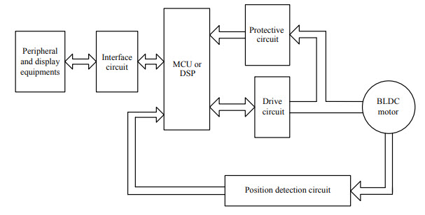
For inductive loads a synchronous condenser is connected towards the load side and is overexcited. Based on the type of input we have classified it into single phase and 3 phase motors. The diagram clearly shows how the reference source PID controller driver circuit sensors converter circuit inverter circuit display scope and motor are interconnected.
Arduino Stepper Motor Position Control Circuit Diagram and Explanation. The slip ring and brush technique do not work for the larger motor and generator. A Stepper Motor is a brushless synchronous motor which completes a full rotation into a number of steps.
The main block diagram and typical application circuit are shown in Figure 3 and Figure 4 respectively. Brushless Vs Brushed MotorExhaustive Facts And FAQs in Tabular Format. The brushless wound-rotor doubly fed motor is a synchronous motor that can function exactly at the supply frequency or sub to super multiple of the supply frequency.
10 Waveform for Each Block. The foundational frequency transferring performance Gs of the PID controller can be represented by 1 and 2 0030 sec. Figure 256 shows the schematic representation of a dc.
When a motor is stopped by a brake for example it is the torque output needed to hold a load as the motor stops. It draws the lagging current from the supply or supplies the reactive power. The voltage signal a is low when the speed detected.
The permanent magnet synchronous motor is cross between an induction motor and a brushless DC motor. Unmatched portfolio of precise analog technologies to control position torque and speed combined with advanced signal processing for accurate real-time motor. It is an electronically controlled commutation system instead of having a mechanical commutation which is typical of brushed motors.
Synchronous condensers make it behave like a capacitor. Unlike the induction motor it can produce torque at synchronous speed without slip. A brushless DC electric motor BLDC motor or BL motor also known as an electronically commutated motor ECM or EC motor or synchronous DC motor is a synchronous motor using a direct current DC electric power supply.
You can see we use a TRIAC to control the voltage. Brush-type and brushless exciters are used to supply the DC field current to the rotor. Designing the 3-Phase Brushless DC Motor.
D flip flop with Synchronous Reset Synchronous Reset d flip flop. For dc supply to the rotor they used brushless exciters. 10 shows the waveforms of each block.
It looks like 3 synchronous buck converters without filter capacitors. Anibal de Almeida Steve Greenberg in Encyclopedia of Energy 2004. We also use a half-wave rectifier.
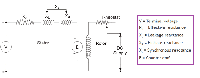
The rotor current establishes a northsouth magnetic pole. The speed set value d and the detected voltage e of the speed generated by a tacho-generator is compared in the comparison amplifier blockThen the level of the voltage signal a is determined. 11 Phasor Diagram of Synchronous Motor In order to draw the phasor diagram Vt is taken as the reference phasor and below points are to be followed.
Various types of synchronous motors Equivalent circuit and phasor diagram of cylindrical synchronous motor Speed-torque characteristics of cylindrical synchronous motor. If a machine works as a asynchronous motor then the direction of armature current will be. We have used the 28BYJ-48 Stepper motor and the ULN2003 Driver module.
The circuit Diagram for the arduino stepper motor control project is shown above. The brushless DC motor is a synchronous electric motor that from a modelling perspective looks exactly like a DC motor having a linear relationship between current and torque voltage and rpm. 3-phase brushless DC motor is shown in Fig.
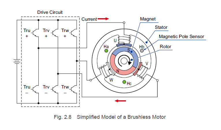
Indicated by speed per minute it is the intrinsic factor determined by number of poles and line frequency. See figure 9 a simplified schematic of a brushless motor driver. Direct Current ExamplesDetailed List of Applications and Examples on.
The most common type of 3 phase motors is synchronous motors and induction motorsWhen three-phase electric conductors are placed in certain geometrical positions ie. However the stator structure with windings constructed to produce a sinusoidal flux density in the airgap of the machine resembles that of an induction motor. Permanent magnet PM motor is a continuous-rotation electromagnetic actuator which can be directly coupled to its load.
The circuit equation for a synchronous motor is thus. The PM motor consists of an annular brush ring assembly a permanent magnet stator ring and a laminated wound rotor. Static Kramer drive and its closed-loop control Introduction to synchronous motor.
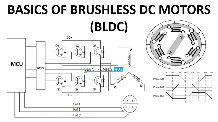
It uses an electronic closed loop controller to switch DC currents to the motor windings producing magnetic fields which effectively rotate in space and. 9 Block Diagram of AC Speed Control Motor System. A simplified diagram of a brushless motor controller.
Synchronous motors as the name implies rotate at a constant synchronous speedThe rotor of this type of motor is a wound rotor which receives the excitation magnetizing current from its excitation system a separate direct current source with controller. So to make 1 turn we need to generate 48 electrical steps. The completed motor.
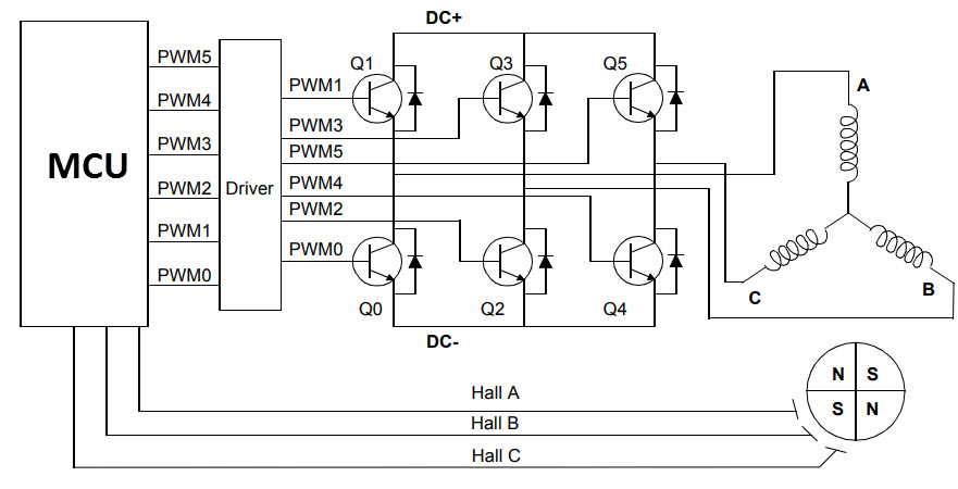
The position sensor used in brushless motor is usually a magnetic sensor Hall element Hall IC. Electrical motors are an electro-mechanical device that converts electrical energy to mechanical energy. The motor used in this application note has 12 teeth poles and 16 magnets.
The main design difference between a brushed and brushless motors is the replacement of mechanical commutator with an electric switch circuit. The brushless exciter is itself an ac generator as any machine has 2 circuitries first is armature and other is field. This is a simplified control circuit diagram for the DSC Series.
For anyone thats interested this is the control circuit diagram with more details. Construction of BLDC Motor. Figure 10 is a picture of an actual electronic speed controller used by quadcopter hobbyists.
Keeping that in mind a BLDC Motor is a type of synchronous motor in the sense that the magnetic field generated by the stator and the rotor revolve at the same frequency. A brushless DC motor known as BLDC is a permanent magnet synchronous electric motor which is driven by direct current DC electricity and it accomplishes electronically controlled commutation system commutation is the process of producing rotational torque in the motor by changing phase currents through it at appropriate times instead of a. Like a brushless DC motor it has a permanent magnet rotor and windings on the stator.
Equivalent circuit and phasor diagram of a synchronous motor per phase Figure 2.

Electric Drives Brushless Dc And Reluctance Motors Description And Applications
Synchronous Automatic Motor Starter


Equivalent Circuit Of Brushless Dc Motor Download Scientific Diagram
Basics Of Brushless Dc Motors Bldc Motors Construction Working

Schematic Of Brushless Dc Motor Drive Download Scientific Diagram

Simplified Diagram Of A Brushless Synchronous Machine With A Hsbds A Download Scientific Diagram

Schematic Diagram Of The Bldc Motor Control System Download Scientific Diagram
The Synchronous Motor

3 Phase Ac Synchronous Generator With Brushless Exciter Circuit Youtube
Basics Of Brushless Dc Motors Bldc Motors Construction Working

Simplified Diagram Of A Brushless Synchronous Machine With A Hsbds A Download Scientific Diagram
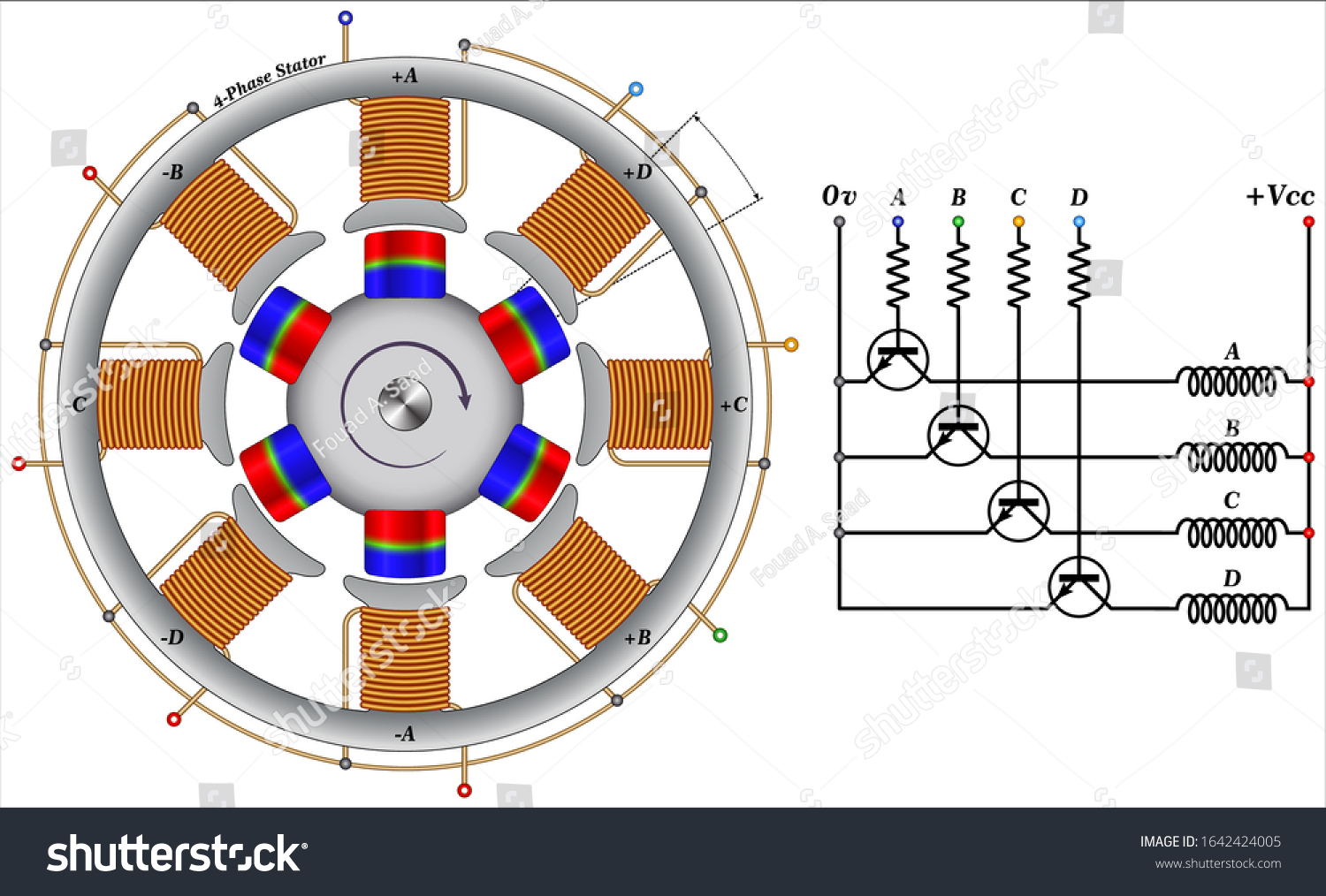
Stepper Motor Brushless Synchronous Electric Motor Stock Vector Royalty Free 1642424005
Technical Manual Series Brushless Motor Structure And Rotation Principles
How Do Brushless Motors Work Quora
Basics Of Brushless Dc Motors Bldc Motors Construction Working

Brushless Dc Motors Bldc What Are They How Do They Work
Industrial Motor Control Synchronous Motors

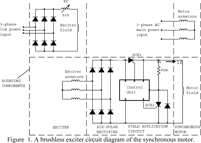
Figure 1 From A Neural Network Based Approach For The Detection Of Faults In The Brushless Excitation Of A Synchronous Motor Semantic Scholar

Schematic Diagram Of The Brushless Exciter Synchronous Machine Download Scientific Diagram